- Drony(207)
- Helikoptery(576)
- Samoloty(2)
- Aparatury i Odbiorniki(274)
- Elektronika(425)
- Silniki - Heli Plane Motor(31)
- Silniki - Multirotor Motor(88)
- Serwa(52)
- Kontrolery FC(61)
- Regulatory ESC(46)
- Regulatory ESC Plane Heli(7)
- Stack FC + ESC(41)
- AIO FC + ESC(21)
- GPS GNSS Compass(18)
- Czujniki - Sensors(15)
- Elektronika(16)
- PDB i BEC(28)
- BEC(22)
- Oświetlenie(18)
- Żyroskopy i FBL(5)
- FPV(308)
- Śmigła(414)
- Łopaty(26)
- Ładowarki(27)
- Akumulatory(74)
- Plecaki i Torby(16)
- Akcesoria(196)
- Komis, usługi(3)
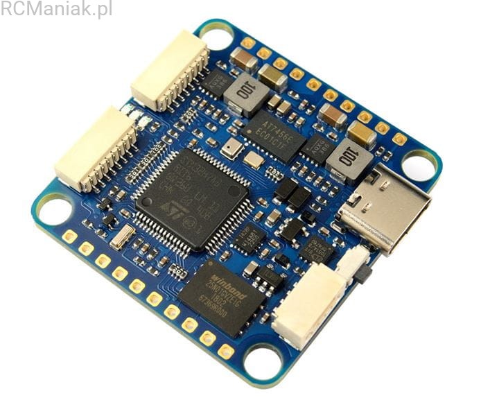
Kontroler Matek H7A3-SLIM Flight Controller
Cena regularna:
towar niedostępny

 Opis
Opis

Specifications
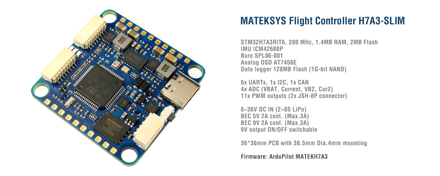
- MCU: STM32H7A3RIT6, 280MHz Cortex-M7, 1.4MB RAM, 2MB Flash
- IMU: ICM42688P
- Baro: SPL06-001
- OSD: AT7456E
- Blackbox: 128MB Flash (1G-bit NAND)
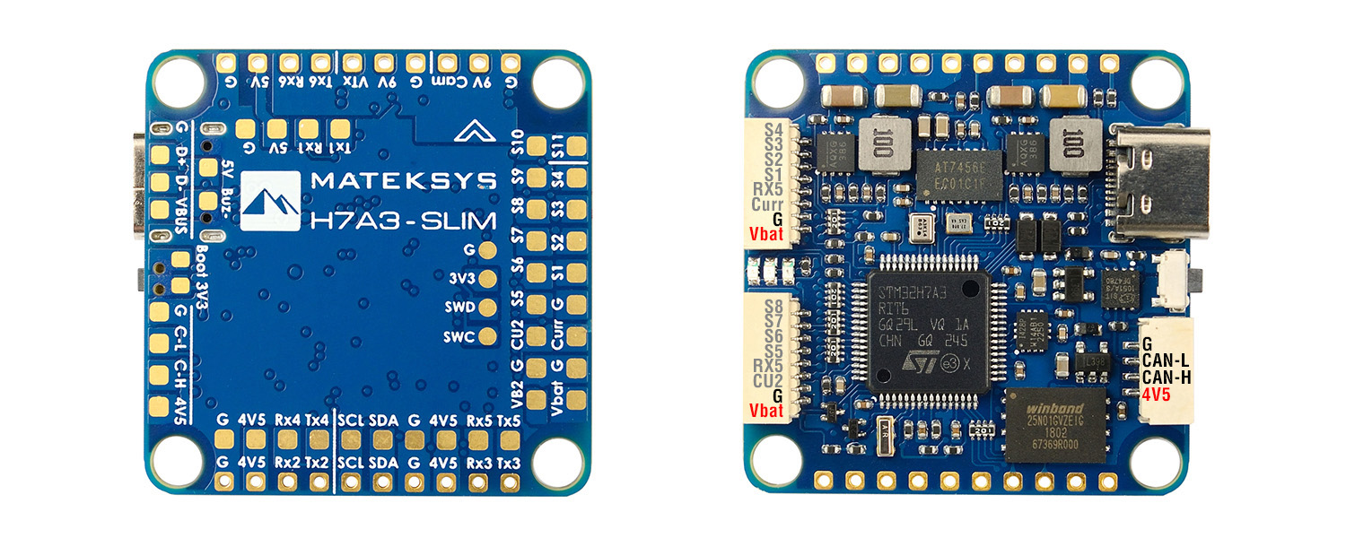
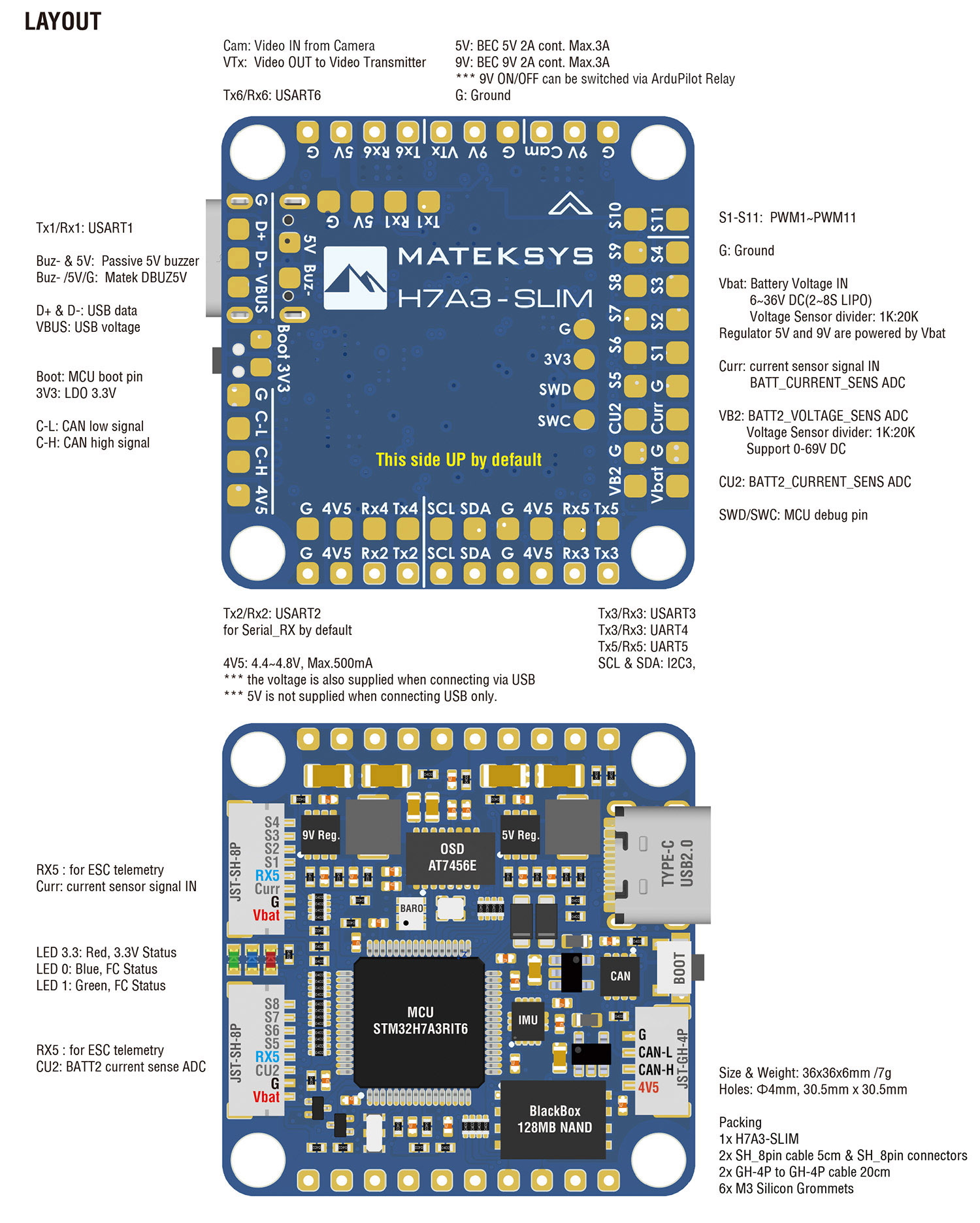
- 6x Uarts (1,2,3,4, 5, 6) with built-in inversion.
- 11x PWM outputs
- 1x I2C
- 1x CAN
- 4x ADC (VBAT, Current, VB2, Cur2)
- 3x LEDs for FC STATUS (Blue, Red) and 3.3V indicator(Red)
- USB Type-C(USB2.0)
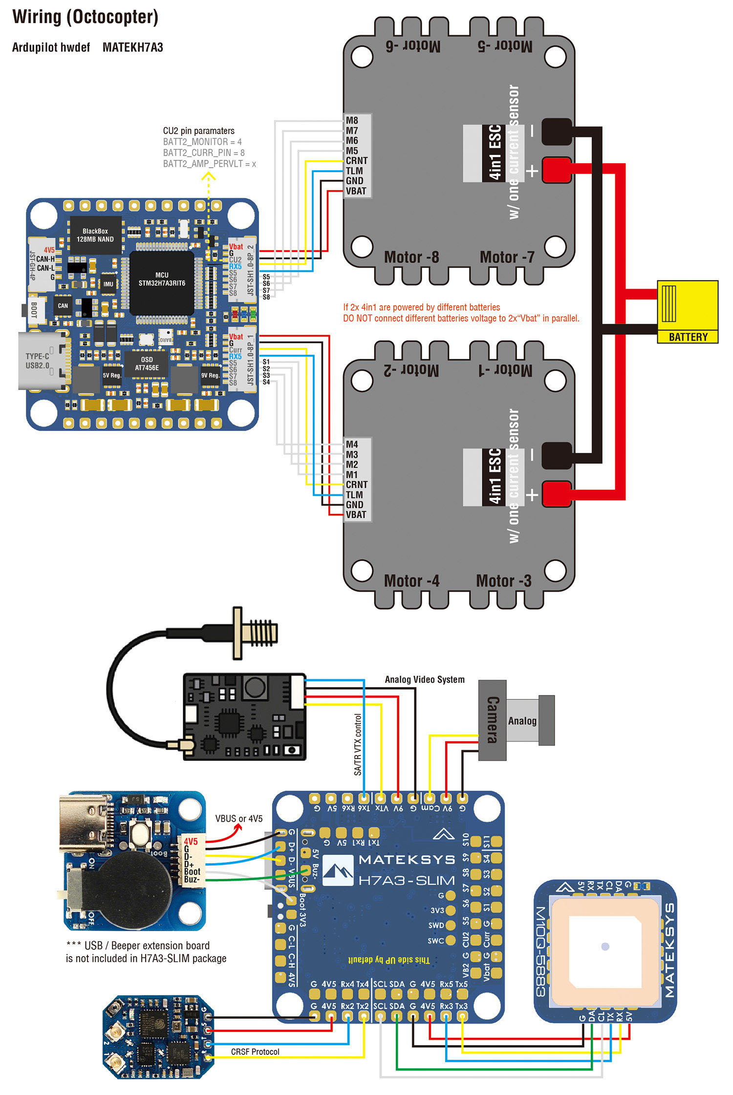
- 8x PWM outputs on 2x JST-SH1.0_8pin connector for 2x 4in1 ESC
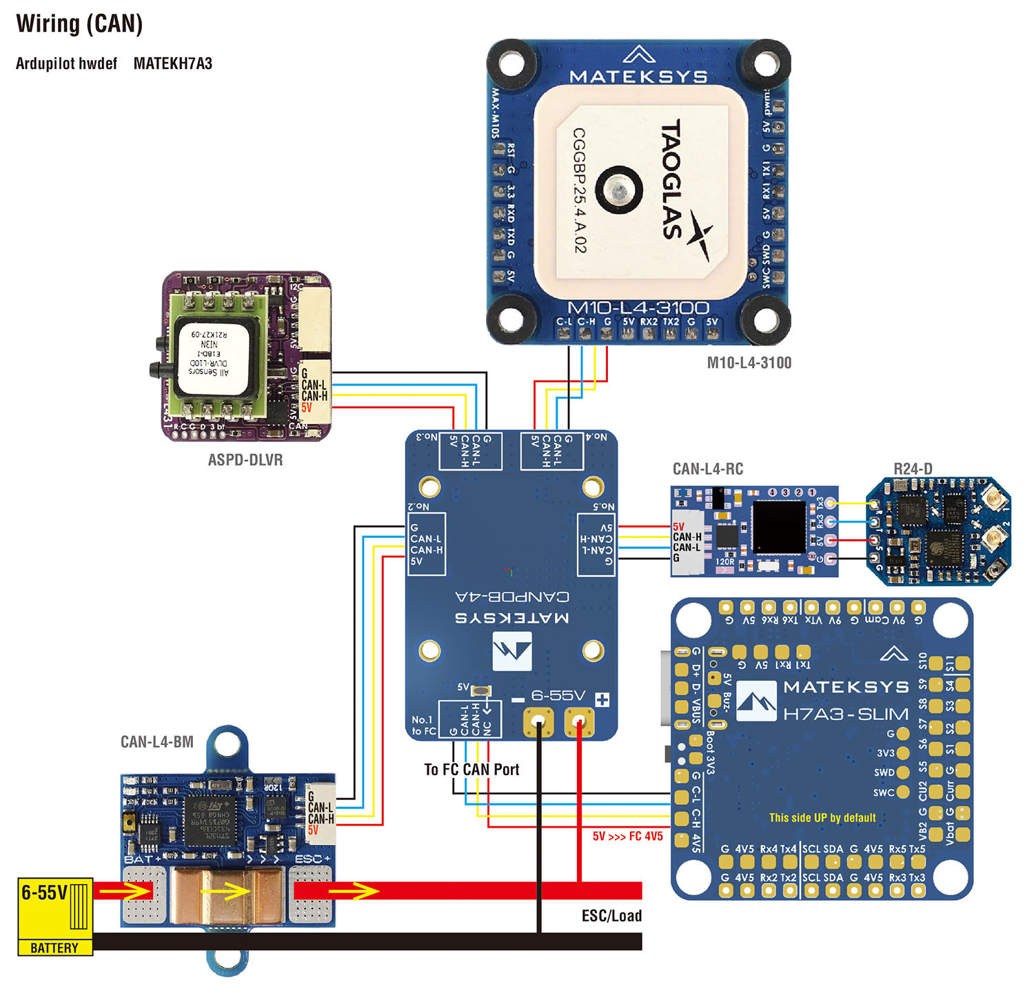
- 1x JST-GH1.25_4pin connector (5V/CAN-H/CAN-L/G)
- 9V output ON/OFF switchable
- Digital video OSD is supported by any spare UART
Power
- Vbat Input: 6~36V (2~8S LiPo)
- BEC: 5V 2A cont. (Max.3A)
- BEC: 9V 2A cont. (Max.3A)
- LDO 3.3V: Max.200mA
- No Current Sensor built-in
- ADC VB2 pad supports Max. 69V (voltage divider: 1K:20K)
FC Firmware
- ArduPilot: MATEKH7A3 (4.6 or newer)
- ArduPlane https://firmware.ardupilot.org/Plane/latest/MatekH7A3/
- ArduCopter https://firmware.ardupilot.org/Copter/latest/MatekH7A3/
- Flashing with STM32CubeProgrammer
Physical
- Mounting: 30.5 x 30.5mm, Φ4mm with Grommets Φ3mm
- Dimensions: 36 x 36 x 5 mm
- Weight: 7g
- 3D step H7A3-SLIM_step.zip
Including
- 1x H7A3-SLIM
- 6x Silicon grommets M4 to M3
- 2x JST-SH1.0_8pin cable, 5cm, & 8pin connectors
- 1x JST-GH-4P to JST-GH-4P cable for CAN port, 20cm
| ArduPilot | ||||||
| PWM | S1 | PWM1 GPIO50 | 5 V tolerant I/O | TIM1_CH2 | DMA/Bi-DShot | Group1 |
| S2 | PWM2 GPIO51 | 5 V tolerant I/O | TIM1_CH3 | DMA/Bi-DShot | ||
| S3 | PWM3 GPIO52 | 5 V tolerant I/O | TIM2_CH1 | DMA/Bi-DShot | Group2 | |
| S4 | PWM4 GPIO53 | 5 V tolerant I/O | TIM2_CH2 | DMA/Bi-DShot | ||
| S5 | PWM5 GPIO54 | 5 V tolerant I/O | TIM3_CH3 | DMA/Bi-DShot | Gourp3 | |
| S6 | PWM6 GPIO55 | 5 V tolerant I/O | TIM3_CH4 | DMA/Bi-DShot | ||
| S7 | PWM7 GPIO56 | 5 V tolerant I/O | TIM3_CH1 | DMA/Bi-DShot | ||
| S8 | PWM8 GPIO57 | 5 V tolerant I/O | TIM3_CH2 | DMA/Bi-DShot | ||
| S9 | PWM9 GPIO58 | 5 V tolerant I/O | TIM4_CH1 | DMA/DShot | Group4 | |
| S10 | PWM10 GPIO59 | 5 V tolerant I/O | TIM4_CH2 | DMA/DShot | ||
| S11 | PWM11 GPIO60 | 5 V tolerant I/O | TIM16_CH1 | DMA/DShot | Group5 | |
| PWM1~PWM11 are Dshot and PWM capable. However, mixing Dshot and normal PWM operation for outputs is restricted into groups, ie. enabling Dshot for an output in a group requires that ALL outputs in that group be configured and used as Dshot, rather than PWM outputs. If servo and motor are mixed in same group, make sure this group run lowest PWM frequency according to the servo specification. That is to say. If Servo support Max. 50Hz, ESC must run at 50Hz in this group. |
||||||
| PINIO | 9V switch | GPIO81 | RELAY1_PIN | 81 | ||
| ADC | Vbat pad | BATT_VOLTAGE_SENS | 6~36V | BATT_VOLT_PIN BATT_VOLT_MULT |
10 21.0 |
|
| Curr pad | BATT_CURRENT_SENS | 0~3.3V | BATT_CURR_PIN BATT_AMP_PERVLT |
11 X |
||
| VB2 Pad | BATT2_VOLTAGE_SENS | 0~69V | BATT2_VOLT_PIN BATT2_VOLT_MULT |
18 21.0 |
||
| CU2 Pad | BATT2_CURRENT_SENS | 0~3.3V | BATT2_CURR_PIN BATT2_AMP_PERVLT |
8 X |
||
| I2C | SCL/SDA | I2C3 | 5V tolerant I/O | on board Baro SPL06-001 | Address | 0x76 |
| Digital Airspeed I2C MS4525 DLVR-L10D |
ARSPD_BUS ARSPD_TYPE ARSPD_TYPE |
0 1 9 |
||||
| Magnetometer | COMPASS_AUTODEC | 1 | ||||
| CAN | C-H/C-L | CAN2 | 5V tolerant I/O | CAN | CAN_D1_PROTOCOL CAN_P1_DRIVER |
1 1 |
| CAN GPS CAN Compass CAN Airspeed sensor |
GPS_TYPE COMPASS_TYPEMASK ARSPD_TYPE |
9 0 8 |
||||
| UART | USB | USB | console | SERIAL0_PROTOCOL | 2 | |
| TX1 RX1 | USART1 w/DMA | 5 V tolerant I/O | Telemetry | SERIAL1_PROTOCOL | 2 | |
| TX2 RX2 | USART2 w/DMA | 5 V tolerant I/O | RC input/Receiver | SERIAL2_PROTOCOL | 23 | |
| TX3 RX3 | USART3 w/DMA | 5 V tolerant I/O | GPS | SERIAL3_PROTOCOL | 5 | |
| TX4 RX4 | UART4 w/o DMA | 5 V tolerant I/O | Spare | SERIAL4_PROTOCOL | -1 | |
| TX5 RX5 | UART5 w/o DMA | 5 V tolerant I/O | Spare | SERIAL5_PROTOCOL | -1 | |
| TX6 RX6 | USART6 w/o DMA | 5 V tolerant I/O | Spare | SERIAL6_PROTOCOL | -1 | |
RC INPUT
RC input is configured on the USART2(SERIAL2). It supports all serial RC protocols. SERIAL2_PROTOCOL=23 by default.
- PPM is not supported.
- CRSF requires Tx2 & Rx2 connection, and set SERIAL2_OPTIONS to “0” (default).
- SBUS/DSM/SRXL connects to the Rx2 pin, but SBUS requires that the SERIAL2_OPTIONS be set to “3”.
- FPort requires connection to Tx2, and set SERIAL2_OPTIONS to “7”. If Telemetry doesn’t work, try set SERIAL7_OPTIONS = 135.
- SRXL2 requires a connection to Tx2, and automatically provides telemetry. Set SERIAL2_OPTIONS to “4”.
- Any UART can be used for RC system connections in ArduPilot also, and is compatible with all protocols except PPM. See Radio Control Systems for details.
ArduPilot Relay(PINIO)
- 9V output ON by default
- PC13 PINIO1 OUTPUT GPIO(81) //9V power switche.g.
- RELAY_PIN 81 // PINIO1 GPIO
- RC7_OPTION 28 //Relay On/Off, Use CH7 of Transmitter to set 9V ON/OFF
The configured feature will be triggered when the auxiliary switch’s pwm value becomes higher than 1800. It will be deactivated when the value falls below 1200.
Check the pwm value sent from the transmitter when the switch is high and low using the Mission Planner’s Initial Setup >> Mandatory Hardware >> Radio Calibration screen. If it does not climb higher than 1800 or lower than 1200, it is best to adjust the servo end points in the transmitter.